- Home
- Inductors
- SMT High Current Inductors
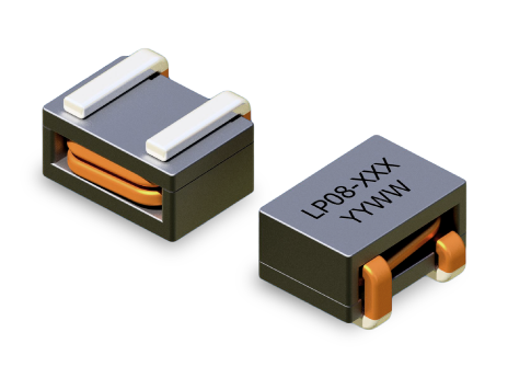
- LP08 Series
Key Features
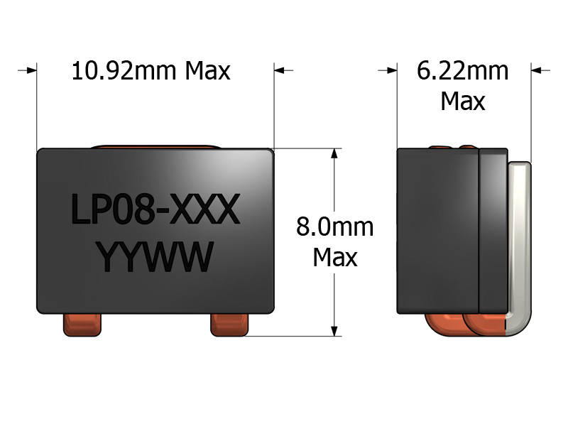
- Footprint 10.92 × 8.00 mm and 6.22 mm height for compact SMT layouts
- Saturation rating up to 45 A for high-current power rails
- Cost-optimized high-current design for budget-sensitive applications
- Inductance values from 210 - 330 nH for efficient rail filtering
- Supports switching frequencies up to 1 MHz for modern converter stages
- Low-cost SMT package supporting automated pick-and-place assembly
APPLICATIONS
- VRMs and POL converters for servers, processors, and SoCs
- High-frequency, high-current DC/DC converters and switching power supplies
- Synchronous buck DC/DC converters supporting high-current rails
- Output chokes and rail filters in compact, space-constrained systems
- Budget-sensitive projects needing a cost-optimized, high-current inductor
Electrical Specifications @ 25°C - Operating Temperature Range1: -40°C to +130°C
Mechanical Drawing
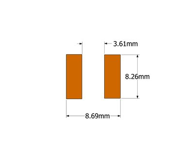
Recommended PCB Layout
Schematic

-
Operating Temp. Range: The combination of ambient temperature and temperature rise.
-
Inductance: Tested at 1MHz, 0.1 VRMS.
-
ISAT: DC current through the winding to cause a 15% (typ) drop in inductance.
-
IDC: DC current through the winding to cause a 40°C (typ) temperature rise at 25°C ambient. PCB layout, trace thickness and width, airflow and proximity to other devices will affect the temperature rise.
-
PACKAGING
- Reel Diameter: 13″
- Reel Width: 24mm
- Pieces/Reel: 600
-
Specifications subject to change without prior notice.
Frequently Asked Questions (FAQs)
How does DC bias affect inductance stability in the LP08?
As the DC current approaches the saturation current (ISAT), the effective inductance of LP08 decreases due to core saturation. When the inductor is operating near its limit, the reduction in inductance increases ripple current. Designers should maintain operational current below ISAT to ensure predictable ripple suppression.
What layout practices improve thermal and electrical performance for LP08?
Wide copper traces, generous copper pours under and around the inductor, and a solid ground plane help spread heat and lower hot-spot temperature. Adding thermal vias under the inductor pads and maintaining airflow near the component further improves thermal performance during high-current operation.
What happens to the LP08 inductor’s performance as temperature rises?
Rising temperature increases winding DCR, which increases conduction losses. This results in slightly higher ripple and lower efficiency. Thermal management through layout and airflow helps mitigate the impact of temperature on performance.
Why is symmetrical routing important when LP08 is used in multiphase converters?
In multiphase designs, unequal trace length or copper cross-section between phases can cause uneven current distribution. Symmetrical routing between phases helps ensure balanced current sharing, minimizing heating differences and improving overall system efficiency.
How does the LP08’s inductance interact with high switching frequencies?
At higher switching frequencies, inductive impedance increases, which can help reduce ripple current. However, core losses also increase with frequency, so designers should verify core loss performance at their target switching frequency to avoid unexpected efficiency degradation.
What should engineers look for when simulating LP08 in a power converter model?
Use realistic models including actual DCR, DC bias inductance derating, and frequency-dependent core loss instead of ideal inductors. This helps generate more accurate predictions for efficiency, thermal behavior, and ripple current.
Is LP08 suitable for controlled peak current events or surge conditions?
LP08 can tolerate short surge conditions within its saturation and thermal limits; however, repeated surges near or above ISAT will cause increased heating and possible degradation over time. A design margin between expected peak current and ISAT is recommended.
What is the impact of nearby high di/dt switching nodes on LP08 performance?
High di/dt nodes can create stray inductive coupling into adjacent traces if layout clearance is insufficient. Maintain spacing between high-di/dt paths and sensitive signal lines, and use ground shielding to minimize unintended coupling.
How does LP08 compare to other SMT inductors in terms of mechanical reliability?
LP08’s molded SMT form provides good mechanical anchoring, but mechanical stresses like vibration or shock can still impact solder joints and leads if the part is placed in highly dynamic environments. Reinforcing the board or using vibration mitigation improves reliability.
What are the trade-offs of using LP08 versus larger power inductors?
LP08 is optimized for compact high-current, high-frequency designs. Larger inductors may offer higher inductance or greater energy storage but at the cost of footprint and mechanical size. LP08 is best where space, automated SMT assembly, and high current capability are prioritized.