- Home
- Transformers
- Gate Drive Transformers
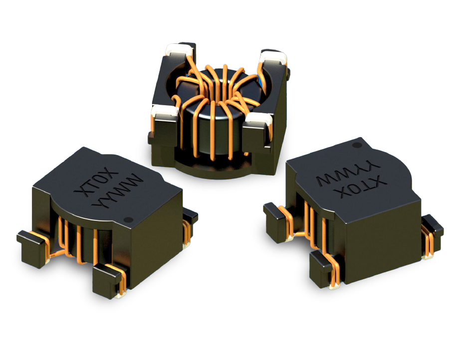
- XT SERIES: Low-Profile SMT Gate and Signal Transformers
Key Features
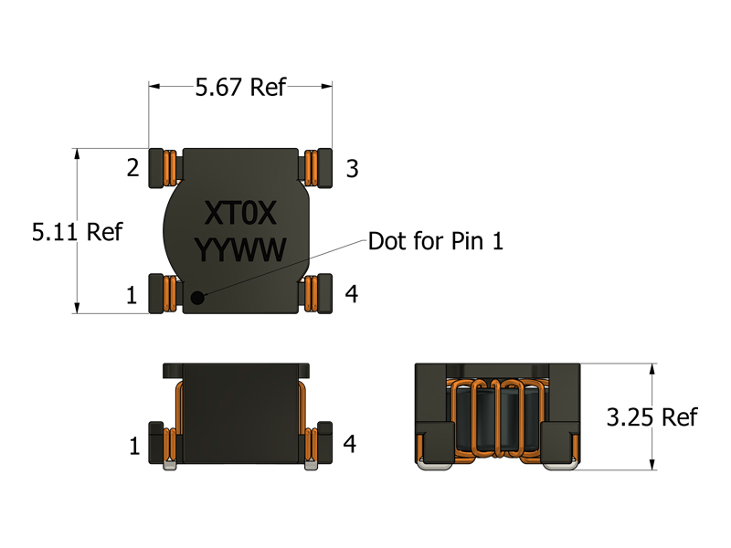
- 3.25 mm ultra-low-profile SMT designs
- Miniature 5.67 mm × 5.11 mm SMT footprint
- Optimized for automated pick-and-place assembly
- Robust 2,350 VDC isolation rating in a compact package
- Low leakage inductance with tight magnetic coupling
- Excellent performance in SiC and GaN switching environments
- The XT04 is designed to work with Infineon's SiC Mosfets, GaN HEMT's and CoolGaN GIT HEMT's.
APPLICATIONS
- High-speed gate drive for SiC MOSFETs and GaN HEMTs
- Isolated pulse and signal transmission for digital communication
- High-density DC/DC converters with strict height constraints
- Signal isolation for feedback loops and sensor interfaces
- Compact industrial motor drives and motion controllers
- Space-constrained battery management systems (BMS)
- Low-power isolated bias generation for floating control and driver rails
Electrical Specifications @ 25°C - Operating Temperature Range1: -40°C to +130°C
Part Number
Turns Ratio
(N1:N2)
Drive Inductance2
(μH, Min)
DCR (Pri:Sec)
(mΩ, Max)
Leakage Inductance
(nH, Max)
ET Product5
(V-μs, Max)
Hi Pot (Drive:Gate)
(VDC)
Mechanical Drawing
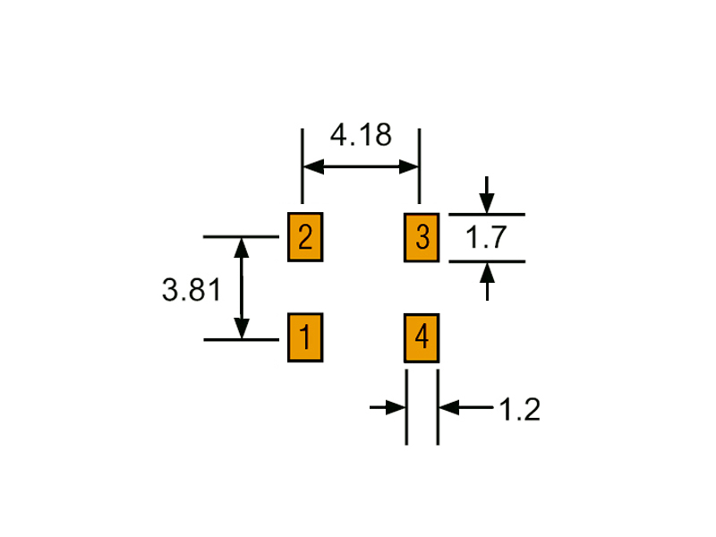
Recommended PCB Layout
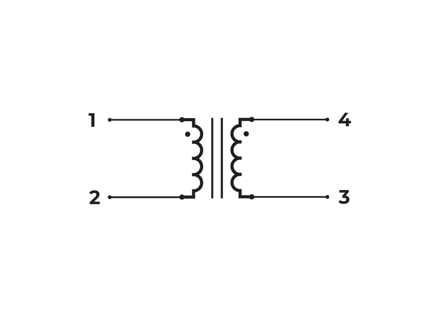
Schematic
-
Operating Temp. Range: The combination of ambient temperature and temperature rise.
-
Drive Inductance: Tested at 100kHz, 0.1 VRMS.
-
SRF: Values are for reference only.
-
Flammability Standard: Meets UL 94V-0.
-
ET Product: The maximum ET is based upon a flux density of 2200 Gauss at 25°C.
ET = EP/2f
Where as, EP = Primary Voltage (V) f = Frequency (Hz) -
Suitable for bipolar applications only.
-
Packaging:
-
Reel Diameter: 13’’
-
Reel Width: 16 mm
-
Pieces/Reel: 1400
-
-
Compliance & Solutions:


-
Specifications subject to change without prior notice.
Frequently Asked Questions (FAQs)
Why does the XT Series support such a wide frequency range from 100 kHz to 5 MHz?
The magnetic core and winding geometry of the XT Series are designed to balance inductance and parasitics so that energy can efficiently transfer at both lower (100 kHz) and very high frequencies (several MHz). This wide range accommodates modern wide-bandgap device switching and high-speed isolated communication without excessive core loss or waveform distortion.
How should the ET product be interpreted when selecting an XT part?
ET product (in V-µs) specifies the Volt-microsecond area the core can support before saturation. XT variants range from about 3.75 V-µs for the XT03 up to 12.80 V-µs for the XT02. Designers should verify that the combination of the expected input voltage and the on-time duration of the pulses does not exceed the ET rating to avoid core saturation and distorted pulse transmission.
What impact does the compact footprint (5.67 × 5.11 mm) and low profile (3.25 mm) have on performance?
The very small footprint and low height support high PCB density and automated pick-and-place assembly, but also mean tighter winding geometry. Tighter geometry tends to lower magnetizing inductance relative to larger transformers and can raise leakage parasitics unless well designed — which is why XT Series parts specify drive inductance, leakage inductance, and SRF to help designers match performance to their switching schemes.
How does leakage inductance vary across XT variants and how does that affect pulse integrity?
XT variants have different maximum leakage inductances (e.g., 150 nH for XT01/XT02, up to 600 nH for XT03). Higher leakage can introduce ringing or overshoot in fast edges, while lower leakage supports cleaner transitions. Designers should choose a variant with leakage suited to their switching speed and acceptable tolerance for voltage ripple.
Why is inter-winding capacitance relevant in the XT Series and what effect does it have?
Inter-winding capacitance (as measured in SPICE parameter data) affects high-frequency response and common-mode noise coupling. Lower capacitance helps maintain isolation between drive and sensed or transmitted signals at MHz switching speeds — important in isolated feedback loops or high-speed digital interfaces.
What does the isolation rating (e.g., 2250–2350 VDC) mean for design safety?
Each XT variant has robust isolation (up to around 2350 VDC drive-to-gate). This rating reflects the transformer’s ability to handle high potential differences between primary and secondary without breakdown. In PCB design, maintaining matching creepage and clearance distances ensures that isolation integrity is preserved in the end product.
How should the DCR values of the XT Series influence driver selection?
The DCR (e.g., 120–350 mΩ range depending on variant and winding) affects resistive loss and current draw from the driver. Lower DCR means lower conduction loss but may also indicate lower magnetizing energy storage. Designers must confirm that the driver output stage can source the required current without saturating or thermally overstressing.
What are the implications of the XT Series’ SRF and how does it relate to usable bandwidth?
Each transformer has a self-resonant frequency (SRF) determined by winding inductance and inter-winding capacitance. Operating too close to SRF can cause impedance peaks, ringing, or attenuation of signal edges. Choosing a variant whose SRF is significantly higher than the intended switching frequency helps maintain linear transformer behavior.
How does the drive inductance of the XT Series influence waveform fidelity?
Drive inductance values (e.g., 31–140 µH) influence how much energy is stored per switching cycle and how cleanly the waveform transfers from primary to secondary. In high-speed gate drive environments, adequate inductance helps suppress distortion and supports consistent pulse amplitude.
How does the compact “flat top” (SMT) design benefit high-density power applications?
The low profile and flat top make the XT Series highly compatible with automated assembly and space-constrained designs, such as multi-phase DC/DC converters or isolated feedback elements in small form-factor power modules. The mechanical footprint enhances board stacking and density without compromising essential isolation or pulse integrity.