


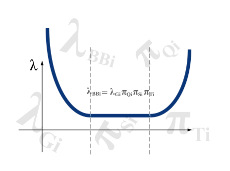
The prediction of the steady-state failure rate for a device is based on a generic steady-state failure rate for the type of device per Telcordia Technologies Special Report SR-332 Issue 3. This generic value is then modified for quality, stress, and temperature. The mean black box steady-state failure rate, λBBi , is:
λBBi = λGiπQiπSiπTi
Where:
- λGi = Mean generic steady-state failure rate for device i (Section 8).
- πQi = 1.0; Quality Factor for device i (Section 9.3).
- πSi = 1.0; Electrical Stress Factor for device i (Section 9.2) based on the percent electrical stress.
If stress is unknown, use 1, which assumes 50% electrical stress. - πTi = 2.0; Temperature Factor for device i at 85°C; Ea = 0.15eV (Section 9.1).
| Hall-Effect Current Sensors | Steady-State FITs (Failures/Billion Hours) | MTBF* (Hours) |
|---|---|---|
| ISB Series (Connector/Lead-Wire) | 94.2 | 10,618,736 |
| ISC Series (Connector/Lead-Wire) | 94.2 | 10,618,736 |
| ISE Series (PCB Mounting) | 94.2 | 10,618,736 |
| Magnetic Components | Steady-State FITs (Failures/Billion Hours) | MTBF* (Hours) |
|---|---|---|
| Gate Drive Transformers (GT and XT Series) | 19.7 | 50,731,486 |
| Current Sense Transformers (CT Series) | 6.0 | 165,722,855 |
| Fixed Inductors (Class D and High Current Power Inductors) | 1.8 | 552,409,518 |
| High Current Inductors (LP Series and Non-Standard Inductors) | 1.8 | 552,409,518 |
- MTBF: Calculated from FITs (MTBF=10^9 (hours) / FITs)
- Hall-Effect Current Sensors FITs : πTi = 1.0; @ 40°C; (Section 9.1)
- Magnetic Components FITs : πTi= 2.0; @ 85°C; Ea = 0.15eV