

- Home
- Transformers
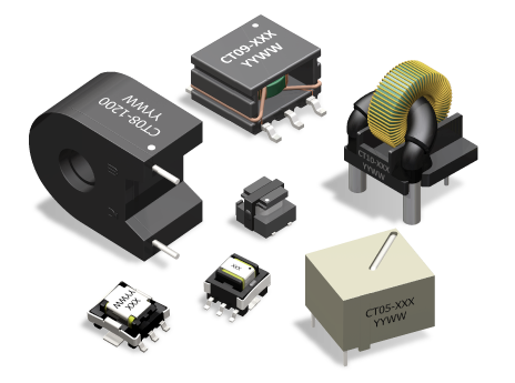
- Current Sense Transformers
Current Sense Transformers
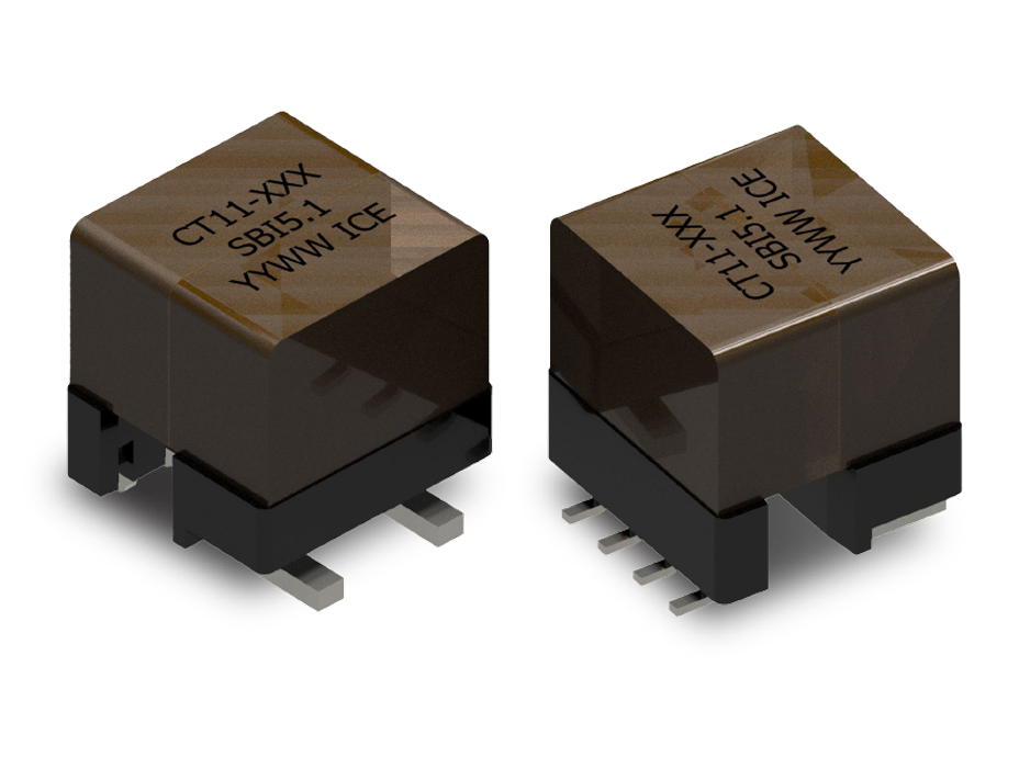
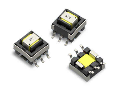
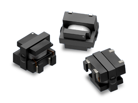
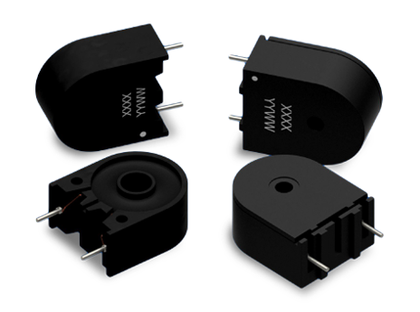
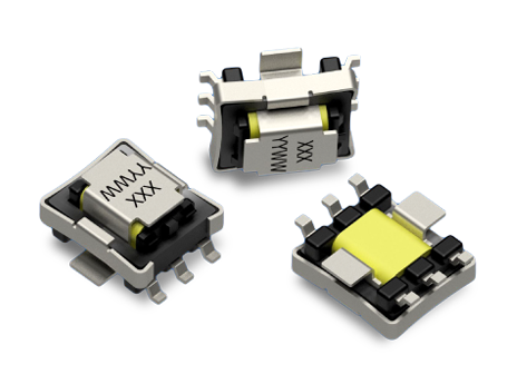
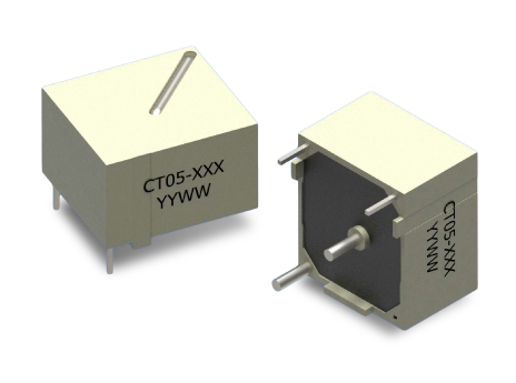
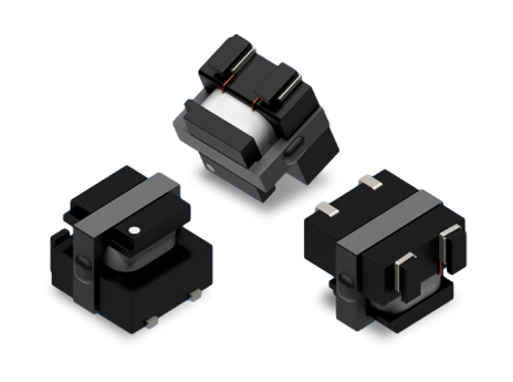
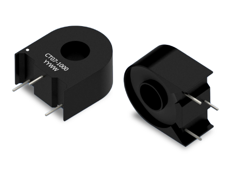
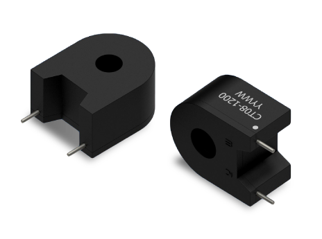
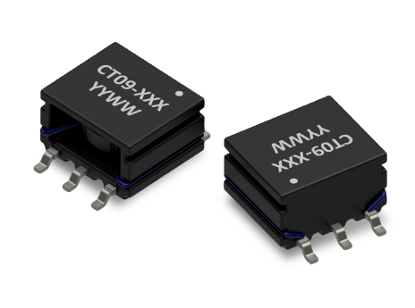
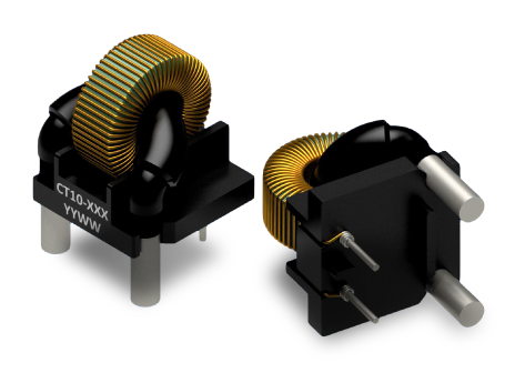
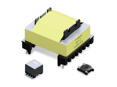
Current sense transformers (CTs) are key components in power monitoring systems, converting high AC currents into manageable values. A typical current transformer comprises a core with a secondary winding. The primary winding can either be integrated into the design or provided via a wire or busbar by the circuit to be measured. When an AC current flows through the primary winding, it generates a magnetic field within the core. This magnetic field, in turn, induces a current to flow through the secondary winding, which is proportional to the primary.
Key applications are in power electronics, where CTs sense current for feedback control and safety systems. By providing a reliable and isolated signal that corresponds to the primary current, CTs enable precise regulation of power delivery. This is particularly important in applications such as motor control, inverters, and power supplies, where controlling current levels is crucial for efficiency, safety, and overall system performance. Additionally, CTs are used in fault detection and protection mechanisms, allowing for the rapid identification of abnormal current levels that may indicate a short circuit or other operational issues.
ICE is a leader in current transformer design, offering a wide range of solutions tailored to various primary currents and ET ratings. Notably, their designs boast high dielectric isolation capabilities and high current measurement options. ICE provides flexibility with standard Surface Mount Technology (SMT) or Through-Hole Technology (THT) options and a choice between feed-through styles and those featuring a built-in primary winding.
Check out our CT application note on selecting the right current sense transformer for DC-DC converter designs — or request a custom transformer tailored to your needs.
 Search Current Sense Transformers